http://www.uml.org.cn/appCase/appCase1218002.htm
Master Java's object-oriented power with the Unified Modeling Language
by Hans-Erik Erikkson and Magnus Penker
The case study in this article provides a feel for how UML is used in the real world. The application, which handles the borrowing and reserving of books and magazines in a library, is large enough to put UML through some realistic paces.
If it were any larger, we couldn't fit it in the magazine.
We analyze and describe the app in an analysis model with use cases and a domain analysis. We expand it into a design model that describes representative slices of a technical solution. Finally, we code a piece of it in Java. (The code, plus the complete analysis and design models are supplied online, in a format readable by the included evaluation copy of Rational Rose.)
Remember that what's shown is only one possible solution. There are plenty of others, and there is no "right" solution for all circumstances. Of course, some solutions will prove better than others, but only experience and hard work will result in that knowledge.
Requirements
Typically, a representative of the end user of the system writes the text requirement specification. For the library application, it looks like this:
- It is a support system for a library.
- A library lends books and magazines to borrowers, who are registered in the system, as are the books and magazines.
- A library handles the purchase of new titles. Popular titles are bought in multiple copies. Old books and magazines are removed when they are out of date or in poor condition.
- The librarian is an employee of the library who interacts with the customers (borrowers) and whose work is supported by the system.
- A borrower can reserve a book or magazine that is not currently available in the library so that when it's returned or purchased by the library, that person is notified. The reservation is canceled when the borrower checks out the book or magazine or through an explicit canceling procedure.
- The library can easily create, update, and delete information about the titles, borrowers, loans, and reservations in the system.
- The system can run on all popular technical environments, including Unix, Windows, and OS/2, and has a modern graphical user interface (GUI).
- The system is easy to extend with new functionality.
The first version of the system doesn't have to handle the message that is sent to the borrower when a reserved title becomes available, nor does it have to check that a title has become overdue.
Analysis
The analysis is intended to capture and describe all the requirements of the system, and to make a model that defines the key domain classes in the system (what is handled in the system). The purpose is to provide an understanding and to enable a communication about the system between the developers and the people establishing the requirements. Therefore the analysis is typically conducted in cooperation with the user or customer.
The developer shouldn't think in terms of code or programs during this phase; it is just the first step toward really understanding the requirements and the reality of the system under design.
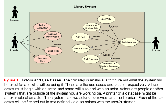
Requirements Analysis. The first step in analysis is to figure out what the system will be used for and who will be using it. These are the use cases and actors, respectively. The use cases describe what the library system provides in terms of functionality: the functional requirements of the system. A use-case analysis involves reading and analyzing the specifications, as well as discussing the system with potential users (customers) of the system.
The actors in the library are identified as the librarians and the borrowers. The librarians are the users of the system and the borrowers are the customers, the people who check out and reserve books and magazines, although occasionally a librarian or another library may be a borrower. The borrower is not intended to directly interact with the system; the borrower's functions are done on behalf of the borrower by the librarian.
The use cases in the library system are:
- Lend Item
- Return Item
- Make Reservation
- Remove Reservation
- Add Title
- Update or Remove Title
- Add Item
- Remove Item
- Add Borrower
- Update or Remove Borrower
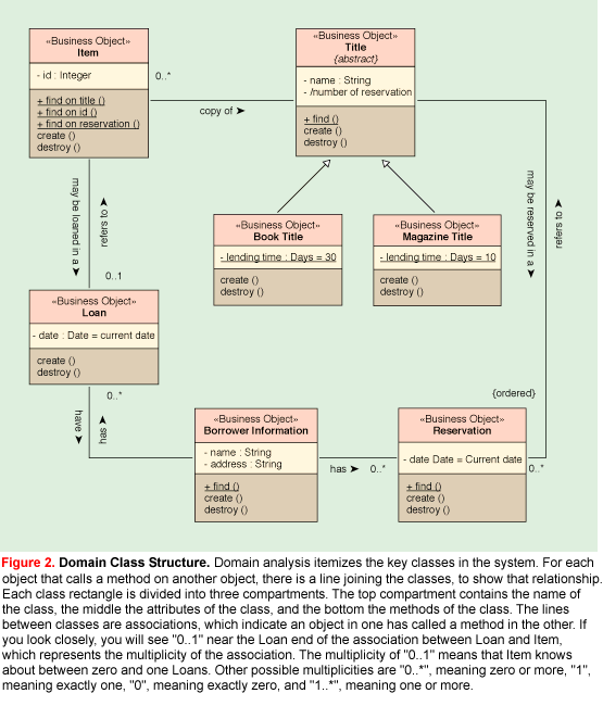
Because a library often has several copies of a popular title, the system must separate the concept of the title from the concept of the item.
The library system analysis is documented in a UML use-case diagram as shown in Figure 1. Each of the use cases is documented with text, describing the use case and its interaction with the actor in more detail. The text is defined through discussions with the user/customer. The descriptions of all the use cases are included online; the use case Lending Item is described as follows:
- If the borrower has no reservation:
- A title is identified.
- An available item of the title is identified.
- The borrower is identified.
- The library lends the item.
- A new loan is registered.
- If the borrower has a reservation:
- The borrower is identified.
- The title is identified.
- An available item of the title is identified.
- The library lends the corresponding item.
- A new loan is registered.
- The reservation is removed.
Besides defining the functional requirements of the system, use cases are used in the analysis to check whether the appropriate domain classes have been defined, and they can be used during the design process to confirm that the technical solution is sufficient to handle the required functionality. The use cases can be visualized in sequence diagrams, which detail their realization.
Domain Analysis. An analysis also itemizes the domain (the key classes in the system). To conduct a domain analysis, read the specifications and the use cases and look at which "concepts" should be handled by the system. Or organize a brainstorming session with users and domain experts to try to identify all the key concepts that must be handled, along with their relationships to each other.
The domain classes in the library system are as follows: BorrowerInformation (so named to distinguish it from the actor Borrower in the use-case diagram), Title, Book Title, Magazine Title, Item, Reservation, and Loan. They are documented in a class diagram along with their relationships, as shown in Figure 2. The domain classes are defined with the stereotype «Business Object», which is a user-defined stereotype specifying that objects of the class are part of the key domain and should be stored persistently in the system.
Some of the classes have UML state diagrams to show the different states that objects of those classes can have, along with the events that will make them change their state. The classes that have state diagrams available online are Item and Title.
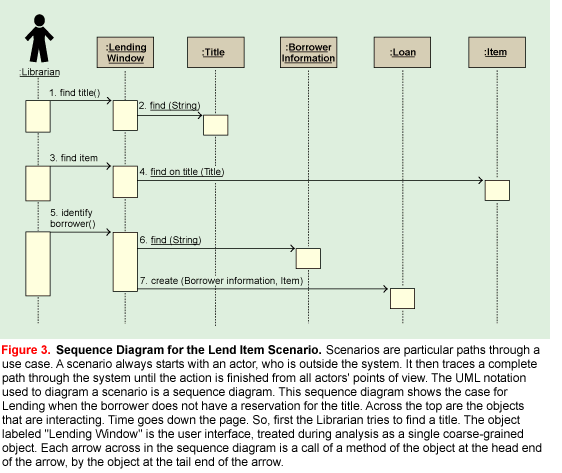
A sequence diagram for the use case Lend Item (the borrower does not have a reservation) is shown in Figure 3. Sequence diagrams for all the use cases are online.
When modeling the sequence diagrams, it becomes obvious that windows or dialogs are needed to provide an interface to the actors. In this analysis, it was sufficient to be aware that interface windows are needed for lending, reserving, and returning items. The detailed user interface is not specified at this point.
To separate the window classes in the analysis from the domain classes, the window classes are grouped into a package named "GUI Package," and the domain classes are grouped into a package named "Business Package."
Design
The design phase expands and details the analysis model by taking into account all technical implications and restrictions. The purpose of the design is to specify a working solution that can be easily translated into programming code.
The design can be divided into two segments:
Architectural design. This is the high-level design where the packages (subsystems) are defined, including the dependencies and primary communication mechanisms between the packages. Naturally, a clear and simple architecture is the goal, where the dependencies are few and bidirectional dependencies are avoided if at all possible. Detailed design. Here all classes are described in enough detail to give clear specs to the programmer who will code the class. Dynamic models from the UML are used to demonstrate how objects of the classes behave in specific situations.
Architecture Design
A well-designed architecture is the foundation for an extensible and changeable system. The packages can concern either handling of a specific functional area or a specific technical area. It is vital to separate the application logic (the domain classes) from the technical logic so that changes in either don't impact the other part. One goal is to identify and set up rules for dependencies between the packages (e.g., "subsystems") so that no bidirectional dependencies are created between packages (in order to avoid packages becoming too tightly integrated with each other). Another goal is to identify the need for standard libraries. Libraries available today address technical areas such as the user interface, the database, or communication, but more application-specific libraries are expected to emerge as well.
The packages, or subsystems in the case study are as follows:
User-Interface Package. These classes are based on the Java AWT package, a standard library in Java for writing user-interface applications. This package cooperates with the Business-Objects package, which contains the classes where the data is actually stored. The UI package calls operations on the business objects to retrieve and insert data into them.
Business-Objects Package. This includes the domain classes from the analysis model such as BorrowerInformation, Title, Item, Loan, and so on. The design completely defines their operations and adds support for persistence. The business-object package cooperates with the database package in that all business-object classes must inherit from the Persistent class in the Database package.
Database Package. The Database package supplies services to other classes in the Business-Object package so that they can be stored persistently. In the current version, the Persistent class will store objects of its subclasses to files in the file system.
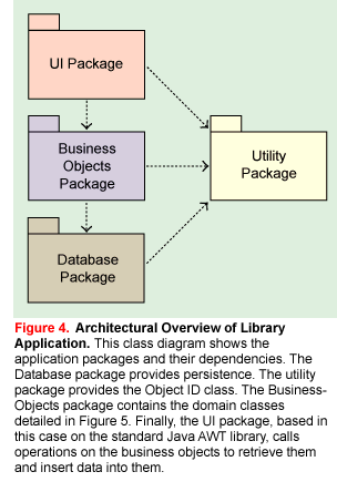
Utility Package. The Utility package contains services that are used in other packages in the system. Currently the ObjId class is the only one in the package. It is used to refer to persistent objects throughout the system including the User-Interface, Business-Object, and Database packages.
The internal design of these packages is shown in Figure 4.
Detailed Design
The detailed design describes the new technical classes—the classes in the User-Interface and Database packages—and fleshes out the Business-Object classes sketched during the analysis. The class, state and dynamic diagrams used are the same diagrams used in the analysis, but they are defined on a more detailed and technical level. The use-case descriptions from the analysis are used to verify that the use cases are handled in the design; sequence diagrams are used to illustrate how each use case is technically realized in the system.
Database Package. The application must have objects stored persistently, therefore a database layer must be added to provide this service. For simplicity, we store the objects as files on the disk. Details about the storage are hidden from the application, which calls common operations such as store(), update(), delete(), and find(). These are part of a class called Persistent, which all classes that need persistent objects must inherit.
An important factor in the persistence handling is the ObjId class, whose objects are used to refer to any persistent object in the system (regardless of whether the object is on disk or has been read into the application). ObjId, short for object identity, is a well-known technique for handling object references elegantly in an application. By using object identifiers, an object ID can be passed to the generic Persistent.getObject() operation and the object will be retrieved from persistent storage and returned. Usually this is done through a getObject operation in each persistent class, which also performs necessary type checks and conversions. An object identifier can also be passed easily as a parameter between operations (e.g., a search window that looks for a specific object can pass its result to another window through an object ID).
The ObjId is a general class used by all packages in the system (User Interface, Business Objects, and Database) so it has been placed in a Utility package in the design rather than in the Database package.
The current implementation of the Persistent class could be improved. To that end, the interface to the Persistent class has been defined to make it easy to change the implementation of persistent storage. Some alternatives might be to store the objects in a relational database or in an object-oriented database, or to store them using persistent-object support in Java 1.1.
Business-Objects Package. The Business-Objects package in the design is based on the corresponding package in the analysis, the domain classes. The classes, their relationships, and behavior are preserved, but the classes are described in more detail, including how their relationships and behavior are implemented.
Some of the operations have been translated into several operations in the design model and some have changed names. This is normal, since the analysis is a sketch of the capabilities of each class while the design is a detailed description of the system. Consequently all operations in the design model must have well-defined signatures and return values (they are not shown in Figure 5 due to space restrictions, but they are present in the model online). Note the following changes between the design and the analysis:
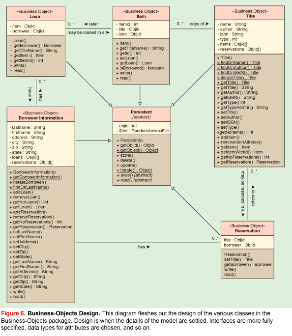
- The current version of the system does not have to check whether an item is returned in time, nor does the system have to handle the ordering of reservations. Therefore the date attribute in the
Loan and Reservation classes has not been implemented.
- The handling of magazine and book titles is identical, except for the maximum lending period, which doesn't have to be handled. The subclasses
Magazine and Book Title in the analysis have thus been deemed as unnecessary and only a type attribute in the Title class specifies whether the title refers to a book or magazine. There's nothing in object-oriented design that says the design can't simplify the analysis!
Both of these simplifications could be removed easily if deemed necessary in future versions of the application.
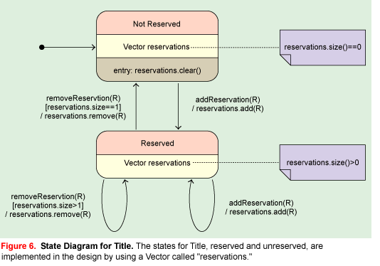
The state diagrams from the analysis are also detailed in the design, showing how the states are represented and handled in the working system. The design state diagram for the Title class is shown in Figure 6. Other objects can change the state of the Title object by calling the operations addReservation() and removeReservation(), as shown in the diagram.
User-Interface Package. The User-Interface package is "on top" of the other packages. It presents the services and information in the system to a user. As noted, this package is based on the standard Java AWT (Abstract Window Toolkit) class.
The dynamic models in the design model have been allocated to the GUI package, since all interactions with the user are initiated through the user interface. Again, sequence diagrams have been chosen to show the dynamic models. The design model's realizations of the use cases are shown in exact detail, including the actual operations on the classes.
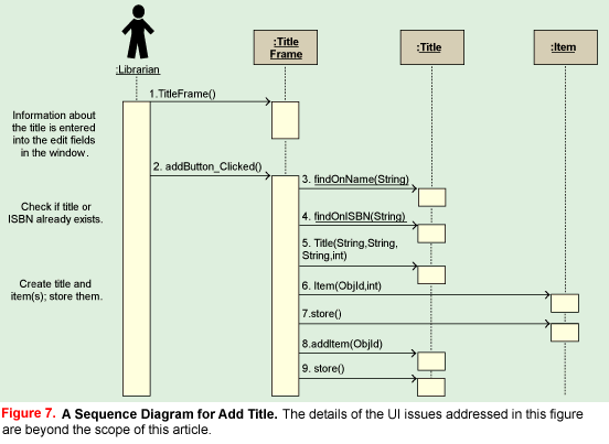
The sequence diagrams are actually created in a series of iterations. Discoveries made in the implementation (coding) phase result in further iterations. Figure 7 shows the resulting design sequence diagram for Add Title. The operations and signatures are exactly as they appear in the code online.
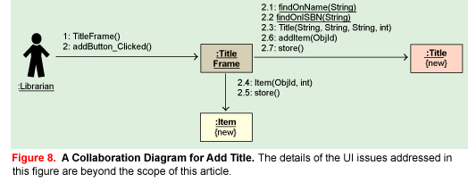
Collaboration diagrams can be used as an alternative to sequence diagrams, as shown in Figure 8.
User-lnterface Design
A special activity carried out during the design phase is the creation of the user interface.
The user interface in the library application is based on the use cases, and has been divided into the following sections, each of which has been given a separate menu bar in the main window menu:
Functions. Windows for the primary functions in the system, that is, lending and returning items and making reservations of titles.
Information. Windows for viewing the information in the system, the collected information about titles and borrowers.
Maintenance. Windows for maintaining the system, that is, adding, updating, and removing titles, borrowers, and items.
Figure 9 shows an example of one of the class diagrams in the user-interface package. This contains typical AWT event handlers. The attributes for buttons, labels, edit fields are not shown.
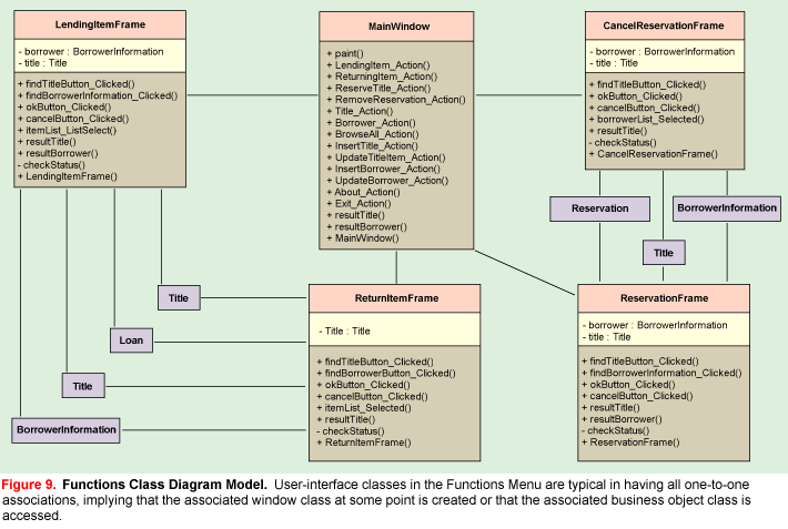
Each window typically presents a service of the system and is mapped to an initial use case (although not all user interfaces must map from a use case). Creating a successful user interface is beyond the scope of this article. The reader is invited to consider the UI code for this application, included online, which was developed using the Symantec Visual Café environment.
Implementation
Programming begins during the construction or implementation phase. The requirements for this application specify that the system be able to run on a number of different processors and operating systems, so Java was chosen to implement the system. Java makes mapping the logical classes to the code components easy, because there is a one-to-one mapping of a class to a Java code file.
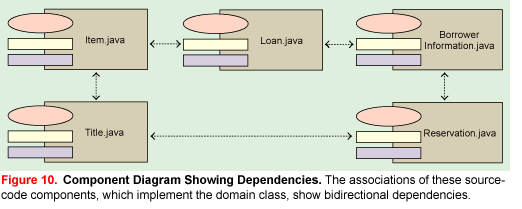
Figure 10 illustrates that the component diagrams in the design model contain (in this case) a simple mapping of the classes in the logical view to components in the component view. The packages in the logical view are also mapped to corresponding packages in the component view. Each component contains a link to the class description in the logical view making it easy to navigate between the different views (even if, as in this case, it is just as simple to use only the filename). The dependencies between the components are not shown in the component diagrams (except for the business objects package) because the dependencies can be derived from the class diagrams in the logical view.
For coding, the specifications were fetched from the following diagrams in the design model:
Class specifications: The specification of each class, showing in detail the necessary attributes and operations.
Class diagrams: The class diagrams in which the class is present, showing its static structure and relationship to other classes.
State diagram: A state diagram for the class, showing the possible states and the transitions that need to be handled (along with the operations that trigger the transitions).
Dynamic diagrams (sequence, collaboration, and activity) in which objects of the class are involved: Diagrams showing the implementation of a specific method in the class or how other objects are using objects of the class.
Use-case diagrams and specifications: Diagrams that show the result of the system are used when the developer needs more information regarding how the system will be used (when the developer feels he or she is getting lost in details—losing sight of the overall context).
Naturally, deficiencies in the design will be uncovered during the coding phase. The need for new or modified operations may be identified, meaning that the developer will have to change the design model. This happens in all projects. What's important is to synchronize the design model and the code so that the model can be used as final documentation of the system.
The Java code examples given here are for the Loan class and part of the TitleFrame class. The Java code for the entire application is available online. When studying the code, read it with the UML models in mind and try to see how the UML constructs have been transferred to code. Consider these points:
- The Java package specification is the code equivalent for specifying to which package in the component or logical view the class belongs.
- The private attributes correspond to the attributes specified in the model; and, naturally, the Java methods correspond to the operations in the model.
- The
ObjId class (object identifiers) is invoked to implement associations, meaning that associations normally are saved along with the class (since the ObjId class is persistent).
The code example in Listing 1 is from the Loan class, which is a business-object class used for storing information about a loan. The implementation is straightforward and the code is simple since the class is mainly a storage place for information. Most of the functionality is inherited from the Persistent class in the database package. The only attributes in the class are the object identifiers for the associations to the Item and BorrowerInformation class, and these association attributes are also stored in the write() and read() operations.
You can examine the addButton_Clicked() operation shown in Listing 2 in the context of the Add Title sequence diagram (Figure 7). Read the code together with the sequence diagram to see that it is just another, more detailed description of the collaboration described by the diagram.
The code for all the sequence diagrams in the design model is included in the source code (the operation and class names are shown in the sequence diagrams).
Test and Deployment
The usefulness of UML doesn't stop when coding ends. Use cases can be tried in the finished application to determine whether they were well supported, for example. And for deployment of the system the models and text of this article make a handy piece of documentation.
Summary
The various parts of this case study were designed by a group of people who made every effort to work in the same manner they would have used on an actual project. And though the different phases and activities might seem separate and to have been conducted in a strict sequence, the work is more iterative in practice. The lessons and conclusions resulting from the design were fed back into the analysis model, and discoveries made in the implementation were updated and changed in the design model. This is the normal way to build object-oriented systems.
This article is excerpted from UML Toolkit, New York: Wiley & Sons, 1998. Hans-Erik Erikkson is a well-known author of books on C++ and OO technology. Magnus Penker is vice president of training at Astrakan, a Swedish company specializing in OO modeling and design.